

Overview
A semi trailer pigtail is the short coiled cable assembly that connects the tractor’s 7-pin receptacle to the trailer’s electrical system, terminating in an SAE J560 plug at each end. For fleet maintenance teams, the pigtail is the most frequently handled electrical component on the trailer—it is plugged and unplugged at every coupling, exposed to road spray and vibration, and is the first suspect when lights flicker or fail.
This FAQ addresses the pinout, wire colors, and diagnostic sequence for the semi trailer pigtail wiring diagram. The pin assignments follow SAE J560, the North American standard for tractor-trailer electrical connections . The pigtail manufacturer’s specification and the tractor’s wiring diagram control the specific vehicle; the color codes below describe the dominant industry convention.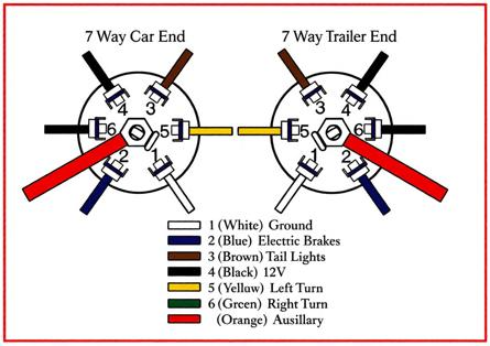
Frequently Asked Questions
What is the pinout for a semi trailer pigtail wiring diagram?
The semi trailer pigtail follows the SAE J560 standard, with seven pins assigned to specific lighting and power functions. The pinout is:
-
Pin 1 — White: Ground return to towing vehicle
-
Pin 2 — Black: Clearance, side marker, and identification lamps
-
Pin 3 — Yellow: Left turn signal and hazard lamps
-
Pin 4 — Red: Stop lamps and anti-lock braking system power
-
Pin 5 — Green: Right turn signal and hazard lamps
-
Pin 6 — Brown: Tail lamps, rear clearance marker, and license plate lamp
This is the standard connector for tractors and semi trailers in the United States and Canada. The SAE J560 standard exists specifically to allow any tractor to be paired with any trailer without custom wiring . The ground pin uses a heavier conductor (8 AWG) than the signal pins because every circuit shares that return path .
What do the wire colors mean on a semi trailer pigtail?
The wire colors correspond to the pin functions: white is ground, black is clearance and side marker, yellow is left turn, red is stop and ABS, green is right turn, brown is tail and license plate, and blue is auxiliary or ABS power . These colors are consistent across major pigtail manufacturers because the SAE J560 standard defines the pin functions and the industry convention applies the colors uniformly.
However, color should never be the sole basis for wiring a replacement pigtail. Wire colors in an aftermarket pigtail may not match the tractor’s harness colors, and a previous repair may have used non-standard wire. The reliable approach is to wire by pin function, not by color—confirm which pin on the receptacle carries which function, and match the pigtail’s pin to that function .
Why does my pigtail have a separate ground wire that is thicker than the others?
The ground wire is thicker because it carries the return current for all six lighting circuits simultaneously. The SAE J560 standard specifies an 8 AWG conductor for the ground pin, compared with 12 AWG for most signal circuits and 10 AWG for the stop/ABS circuit . When the brakes, turn signals, and marker lights are all active, the combined current returns through the single ground path.
A ground wire that is undersized, corroded, or poorly connected produces the most common pigtail fault: multiple lights behaving erratically at once. A dim or flickering output across several functions points to the ground, not to the individual lamps. The ground connection at both the pigtail plug and the trailer receptacle must be clean and tight.
How do I test a semi trailer pigtail for continuity?
Test the pigtail by checking continuity between the corresponding pins at each end with a multimeter set to resistance or continuity mode. With the pigtail disconnected from both the tractor and the trailer, each pin on one plug should show near-zero resistance to the same pin on the other plug.
The test sequence should cover all seven pins: ground (Pin 1), clearance (Pin 2), left turn (Pin 3), stop/ABS (Pin 4), right turn (Pin 5), tail (Pin 6), and auxiliary/ABS (Pin 7). A reading of infinite resistance or a fluctuating reading indicates a broken conductor inside the coiled cable—a common failure mode where the wire strands fatigue from repeated flexing. Flex the cable while testing to reveal intermittent breaks that do not appear when the cable is static.
What causes a pigtail to fail and how can I prevent it?
Pigtails fail from conductor fatigue at the flex points, corrosion at the pins, and physical damage from being run over or crushed. The coiled cable is designed to stretch and retract thousands of times, but the wire strands inside eventually break at the point where the cable enters the plug body.
Prevention practices include:
-
Support the pigtail during coupling: Do not let it hang from the plug or drag on the ground.
-
Inspect the strain relief: The point where the cable meets the plug is the first place a break develops.
-
Clean and grease the pins: Dielectric grease on clean pins excludes moisture and slows corrosion .
-
Replace rather than repair: A pigtail with exposed conductors or a damaged plug body should be replaced, not taped.
Can I use an RV 7-way pigtail on a semi trailer?
No. A semi trailer uses the SAE J560 round-pin connector with separate circuits for stop, left turn, and right turn, while an RV uses a 7-blade connector with combined stop/turn circuits. The two are not electrically compatible and cannot be connected without a converter .
The semi pigtail’s red pin (Pin 4) carries stop lamps on a dedicated circuit, and the yellow and green pins carry the turn signals separately. An RV connector combines stop and turn on the same pins, which is why a converter is required to connect an RV trailer to a semi tractor or vice versa . Using an RV pigtail on a semi trailer will produce incorrect lighting functions and may damage the tractor’s lighting module.
Conclusion
The semi trailer pigtail wiring diagram comes down to the SAE J560 pinout: white ground, black clearance, yellow left turn, red stop/ABS, green right turn, brown tail, blue auxiliary. The ground wire is heavier because it carries the return current for every circuit, and a faulty ground is the most common cause of erratic lighting. Test continuity across all seven pins before condemning a pigtail, flex the cable during the test to reveal intermittent breaks, and wire by pin function rather than by color. The pigtail is a consumable item that fails from fatigue and corrosion, and replacement—not repair—is the appropriate response to a damaged cable.